
The intelligent busway system consists of busbar trunking system, intelligent busbar joint device, intelligent busbar plug-in box , power carrier to wireless device, and remote monitoring and early warning management platform.
System composition The intelligent busway system consists of busbar trunking system, intelligent busbar joint device, intelligent busbar plug-in box , power carrier to wireless device, and remote monitoring and early warning management platform. The schematic diagram of ZN ML-IV intelligent busway system is as follows:
| Product performance Busbar joint monitoring module 1. Online monitoring of temperature and environmental humidity on the surface of busbar joints. 2. The monitoring data is transmitted through the busbar conductor using power carrier technology to the busbar terminal filtering wireless transmission module system, and the collected data is sent to the monitoring module system through radio waves. 3. The measuring device installed on the busbar body adopts a self powered mode and has a success indication. 4. Equipped with on-site data display function and built-in RS485 backup communication interface. 5. The data is displayed on a LCD screen. |
Plug-in box measurement and control module Real temperature monitoring can be performed on the same pin N, A, B, and C inside the plug-in box; prevent the occurrence of abnormal local temperature rise. 2. Monitor real-time output current, voltage, power and other power parameters of phase A, B, and C conductors in the plug-in box. 3. Control the opening and closing of circuit breakers in any plug-in box through the backend computer system, and display the operating status of circuit breakers in each plug-in box in real-time on the computer. 4. The plug-in box measurement and control module has an anti damage function to prevent manual cutting of control lines, and adopts a self- protection function. The system will automatically cut off power. 5. All communication data of the plug-in box monitoring module is transmitted through the main busbar in the busway system using power carrier technology, and finally transmitted to the background measurement and control main station monitoring software system through wireless waves. |
|
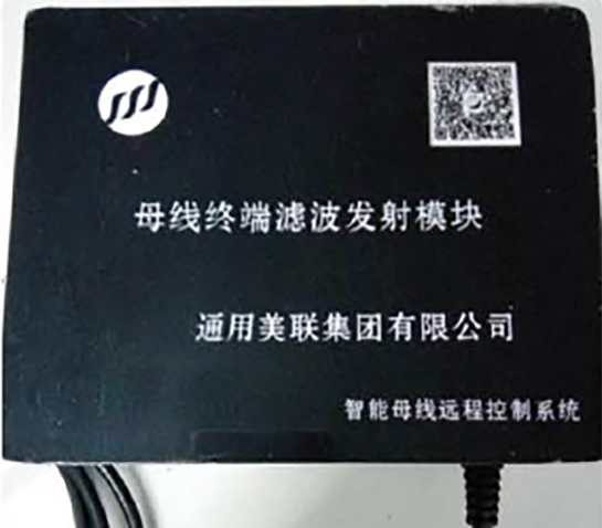
Busbar terminal filtering wireless transmission module Collect monitoring data transmitted in the main busbar conductor of busway system and send it through wireless wave transmission. Filter out clutter data on power lines, collect effective monitoring data and transmit it. 3. Receive wireless command data transmitted by the backend system, convert it into a carrier signal, and input it into the main busbar conductor in the busway system to achieve data reception and transmission functions. |  |